RoeTest, professional tube testing system, tube tracer

RoeTest - professional tube testing system  RoeTest  (Röhrentest)

     professional tube testing system  (c) Helmut Weigl

menu
RoeTest Röhrenmessgerät - home tube testing system
Aktuelles und Historie zur Internetseite - history and news of tube tester
Videos
tube test hardware
Software - Messsoftware und Datenbankensoftware - tube measurement software
Beschreibung - description of tube tester
Beispiele - besondere Röhrenmessungen - examples tubetest
Download Software - free download tube software and tubedata
Bestellung - ordering informations
andere RoeTest's - tube testers made by other people
Identifizierung von Röhren - tube identification
Tipp's Informationen Hilfe - help and documentation
FQA about tube tester and tube measurement
Errata
Haftung, Copyright, warranty
tube links
Impressum
sonstiges - alles was nicht unbedingt mit Röhrenprüfung zu tun hat - misc. Pfeil<

english infos about tube test
english infos


Explication en langue franç
aise

Istruzioni in Italiano


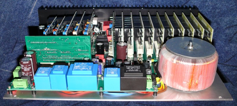
RoeTest V8
- noch kompakter, noch leistungsfähiger, noch einfacher aufzubauen
- even more compact, more powerful, even simpler to assemble

RoeTest V8 - professional tube testing system


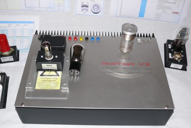
Die Elektronik ist eine kompakte Einheit, welche in ein beliebiges Gehäuse eingebaut werden kann (siehe diverse Aufbauvarianten unter andere RoeTests). Ich habe mich hier für ein Stahlblechgehäuse, rückseitigem großen Kühlkörper und eine CNC-gefräste 3mm Frontplatte entschieden.

The electronics assembly is a compact unit that can be mounted in an arbitrary housing (see the various assembly variants at andere RoeTests).
I decided to use a steel sheet case with a large heat sink at the backside and a CNC milled 3mm front panel.


Änderung V8 gegenüber V7.2

Changes V8 compared to V7.2:

1.      Verkleinerung der Hauptplatine. Diese ist nur mehr 39 cm lang und passt gerade noch in ein Stahlgehäuse mit 40 cm Länge.

2.      Durch die kürzere Hauptplatine wurden wieder einige cm Leitungslänge gespart.

3.      Für die positive 320V Festspannung wurden die bisher 4 Trafos ersetzt durch zwei Trafos und dafür eine Spannungsverdopplung eingebaut (spart Platinenfläche)

4.      G1 + G3-Spannung: Diese beiden Spannungsquellen gehen jetzt bis -63 V(vorher -51V)

5.      Messbereich Heizstrom 6,1 A (bisher 5,1A). Der größere Messbereich kann erhöhte Einschaltströme besser anzeigen. Achtung: An der dauer- Stromlieferfähigkeit von 5 A hat sich nichts geändert (nur kurzzeitig sind auch 5,5A erlaubt). Lediglich der Messbereich wurde erhöht.

6.      Messbereich Anodenstrom 300 mA. Achtung: An der Dauer-Stromlieferfähigkeit von 250 mA (nur kurzzeitig sind 300 mA erlaubt) hat sich nichts geändert. Mit der Änderung werden jetzt kurze Spitzen angezeigt. Vorteil bei der Kennlinienaufnahme: Da hier ja nur kurzzeitig ein hoher Strom fließt, können künftig Kennlinien bis 300 mA aufgenommen werden.

7.      Messbereich G2-Strom 60 mA. Achtung: An der Dauer-Stromlieferfähigkeit von 50 mA (nur kurzzeitig sind 60 mA erlaubt) hat sich nichts geändert. Mit der Änderung werden jetzt kurze Spitzen angezeigt. Vorteil bei der Kennlinienaufnahme: Da hier nur kurzzeitig ein hoher Strom fließt, können künftig Kennlinien bis 60 mA aufgenommen werden.

8.      600V-Karte: Neue Schaltung mit Regelung (bisher nur Stabilisierung). Die Spannung ist damit bei Last ultrastabil (wie bei den anderen Karten). Ein weiterer Vorteil ist, dass die Bauteile auf der Karte kühl bleiben (bisher war wegen der Mindestlast des Spannungsreglers etwas Verlustleistung zu verbraten).

9.      Adapter für USB-Chip. Damit verliert auch das Einlöten des winzigen USB-Chips seinen Schrecken. Bei einem Fehlversuch kann man einfach eine andere Adapterplatine verwenden.

10. Mehr Masseflächen (auflöten von zusätzlichem Kupferdraht entfällt)

11. Dämpfungsglieder am Fassungsboxanschluß. Damit kann meist auf zusätzliche Ferrite in den Fassungsboxen verzichtet werden.

  1. Reduction in size of the motherboard. This is now only 39 cm long and just fits in a steel sheet housing with 40 cm length.
  1. Due to the shorter motherboard again some cm wire length have been saved.
  1. For the fixed 320V supply the previously used 4 transformers have been replaced by two transformers in combination with a voltage doubler (saves board space).
  1. The G1 + G3 voltage range has been extended to -63 V (previously -51V) .
  1. The measuring range for heater current has been extended to 6.1 A (previously 5.1 A). Due to the larger measurement range large inrush currents can be shown better. Note: The long term current capability of 5A has not changed (only for brief periods currents up to 5.5A are allowed). Only the measuring range has been increased.
  1. The measuring range for the anode current has been extended to 300 mA. Note: The continuous current capability is still 250 mA (300 mA for short periods is allowed). With this change short peaks can now be displayed. This gives an advantage for the recording of characteristic curves. As there is only a short-period high current flow curves up to 300mA can be recorded with the V8 now.
  1. The measuring range for the G2-current has been extended to 60 mA.Note: The continuous current capability of 50 mA (60 mA is only briefly allowed) has not changed. With this changes in V8 short peaks up to 60mA can be displayed. The advantage for recording characteristic cuves is: For short period high current flows now curves up to 60mA can be recorded with the V8.
  1. 600V card: New circuitry with control loop (so far only stabilization). Thus the voltage at the load is ultra-stable (as with the other cards). Another advantage is that the components on the board stay cool (previously a small amount of power was wasted due to the minimum required load of the voltage regulator).
  1. Adapter board for the USB chip. Now soldering the tiny USB chip to the motherboard loses its horror. When an attempt fails you can just use another adapter board; no damage is done to the motherboard.
  1. More ground trace surface. Soldering on additional copper wire to carry the high currents is no longer needed.
  2. Better RF attenuation elements at the socket box terminal. This means that in most cases no ferrite beads are required in the socket boxes themselves.


Details zu technischen Daten und Beschreibung finden Sie hier.  Here you can see  technical data and more
description.


Die neue Hauptplatine:
Viele Lötstellen, aber einfach zu bestücken:
- Bestückungsdruck
- kein SMD (bis auf FT232)
- keine Lötbrücken
- minimale externe Verdrahtung


Abmessungen:
39 x 25,4 cm


The new main board:
Many soldering joints
but easy to assemble:
- assembly imprint
- no SMDs (except FT232)
- no jumpers
- minimal external wiring

Size:
39 x 25.4 cm
FT232RL Adapter


Der FT232RL sitzt nun auf einem Adapter und wird auf die Hauptplatine gesteckt.


The FT232RL chip is now located on an adapter board that is plugged to the main board.


Am Fassungsboxanschluss befinden sich Dämpfungsglieder aus HF-Drosseln und je einem 100 Ohm Widerstand (parallel). Diese sorgen für gute Schwingungsunter- drückung, so dass in den Fassungsboxen meist keine Ferrite mehr nötig sind. Die Fassungsboxen, sind deshalb sehr einfach aufzubauen.


At the socket box connector there are attenuator
elements each consisting of a RF choke and a 100 ohms resistor (in parallel). These provide good supression of oscillations so that there is no need for additional ferrite beads in the socket boxes in most cases. Therefore the socket boxes are very easy to build.
Die Elektronik ist sehr kompakt und wird wieder auf der Rückseite der Frontplatte befestigt

The electonics circuitry is very compact and
is mounted to the backside of the front panel as before.
Die MosFet's befinden sich in dieser Ausführung auf einem großen Kühlkörper. Ein Lüfter ist nicht notwendig.

Die Frontplatte ist nur mehr 3 mm stark und damit günstiger.

With this model the MOS-FETs are mounted to a large heat sink. A fan is not required.

The front panel is now only 3mm thick and
hence is cheaper.
Die komplette Einheit habe ich in ein Stahlblechgehäuse eingebaut.

I mounted the entire unit in a steel sheet housing.
Um das RoeTest leicht transportieren zu können, habe ich eine Befestigung für einen Tragegurt angebaut. Diese Befestigung besteht nur aus einer Schraube durch den Kühlkörper. Einfach und effektiv.

Simple fastening of a carrying strap by a screw to through the heatsink.


Bauanleitungen:   Construction manuals:

 Bauanleitung V8 - deutsch.pdf                                           

construction manual RoeTestV8 - english.pdf


Bauteiledatenbank: components database:

bauteile8.1.zip  Bauteilebank RoeTest V8 - Stand 08/2015  - download - in leeren Ordner auspacken und 'bauteile.exe' starten.
 
Components database RoeTest V8.1 - date 08/2015 -  download and unzip to an empty folder, then start 'bauteile.exe'